Toroid Construction (1)
An alternative method of construction used my Mark, a Dutch coiler, can be seen on my page Here
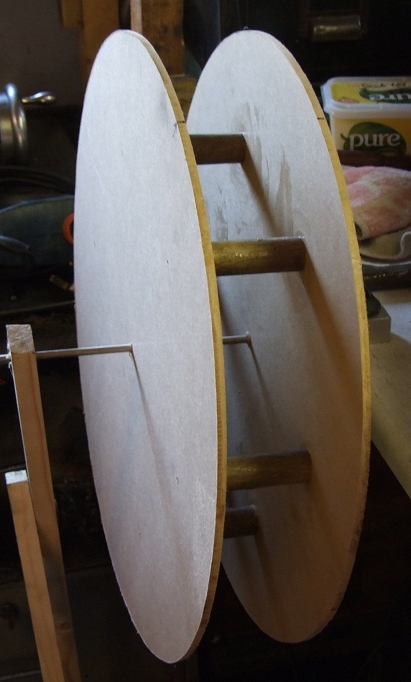
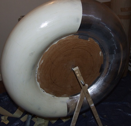
Firstly I made a wooden former to hold the ducting. Some simple mathematics will give the overall diameter needed to achieve your desired finished size.
I decided on a 3.5 inch spacing between the two discs, so it worked out that my discs needed to be 18.8 inches diameter. With the 8.5 inch ducting I was using, this meant I would achieve my overall size of 34.5 inches. The 3.5 inch spacing was chosen because it ensured that the duct, once mounted, could not slip out too easily before it was hot-glued in place.
The two discs are easily cut out with a jig-saw from some thin flat MDF (Medium-density fibre-board).
MDF being the material of choice because it always comes with a good flat finish.
I then clamped the two discs together, and drilled six evenly spaced holes through both pieces, with a drill that was considerably smaller than the fixing nails I was going to use. For the six spacers in the middle I then used round wooden rod, (an old broom handle).
I then cut each rod accurately using a lathe, so that both ends were exactly square, and the rods were all equal in length. Then using the lathe, to again ensure accuracy, I centre drilled a tiny locating hole in both ends of each of the six rods.
Then with some nails that I had tapped through the tiny previously drilled holes in the discs, I could easily locate them in the centre drilled holes of the wooden rods, before tapping the nails in.
Plenty of wood glue formed the main fixing though, as the nails were primarily only used for location.
This method, which although at first sight does seem lengthy, does ensure that both discs are mounted exactly true to one another, which is most important.
A new 8.5 x 34.5 Toroid for the "The Phoenix"
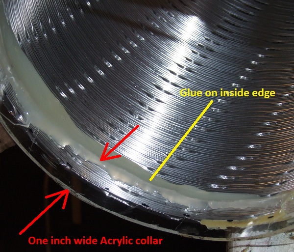
I then found a piece of Acrylic tube that was slightly larger than the inside of the duct. I then cut a section out, so that it fitted snugly inside with the ends butted together. Then using a hot glue gun I sealed the inside edge into the duct. This must be a good strong bond, as the initial forces when mounting the duct on the wooden former, will want to try to pull this joint apart.
This type of duct comes in a compressed form and will stretch to about twice its uncompressed length, so by applying a bit of stretch before assembly, you will find it easier to slip onto the wooden former. Too much stretch though and it will be loose, whilst not enough will mean it is impossible to mount.
I knew from the past that it's easy to stretch, but it's fairly difficult to compress back again without leaving it misshapen, so I took it slowly.
Next I applied a very slight curve to the two ends that will butt together otherwise they will meet dead straight and look wrong. I then pushed the free end of the duct onto the previously glued Acrylic collar and applied plenty of hot glue.
The trouble with hot glue is that it is hard to apply beforehand as it sets so quick, so I had to carefully inject hot glue into the butt joint I had just made, doing just a small section at a time. An extra pair of hands is useful at this stage.
You also need to make sure you apply the hot glue to the duct's end faces, and not too much on the outside surfaces, as the coating of filler that you later apply, won't stick to it.
Because of the stress applied to this joint during the mounting process, I also applied a big blob on the outside surface of its inside curve (where it won't be seen, hidden inside the wooden former) and also opposite on the actual outside curve of the duct. This last blob can be seen however, so it is just a temporary measure. You can cut it down level afterwards (needs a really sharp blade) once the duct has been mounted and fully hot glued in place.
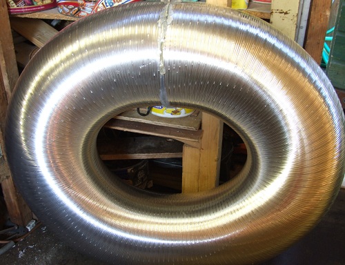
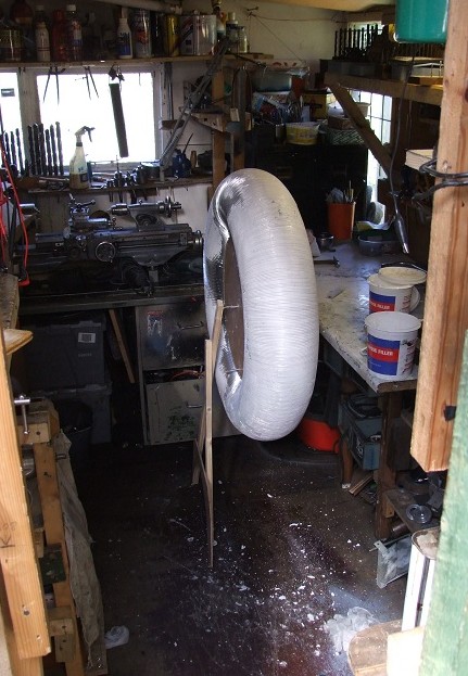
You should now have a floppy tyre made of ducting, ready to be popped onto your wooden rim that you made first of all.
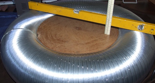
Once the duct was on the wooden former I carefully levelled and squared it up before applying a good solid bead of hot glue around the edge of the MDF's circumference (both pieces).
This needs to be a good joint as the fully finished toroid weighs 16 pounds (10Kg) once all the filler had been applied.
The sealing bead of hot glue mentioned above, will now need to be roughened with sandpaper to help the filler stick.
Once both sides have been glued and completely cooled, you can then cut away with a sharp knife the blob of temporary glue applied to the outside curve. The main task of holding the tube in place having now been taken by the two beads around the MDF's circumference.
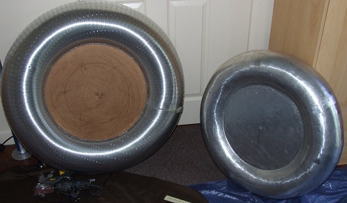
Here you can see the unfinished 8.5" (left) and my current 6" alongside one another.
Shown here is the messy stage of applying several coats of filler, to give a smooth base surface for the Aluminium foil.
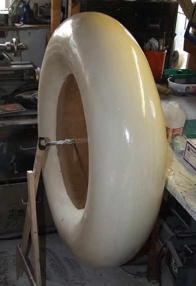
Here we have the new toroid after several coats of filler have been applied and sanded down. A coat of varnish has been applied, this being needed to ensure the Aluminium foil will stick to the filler.
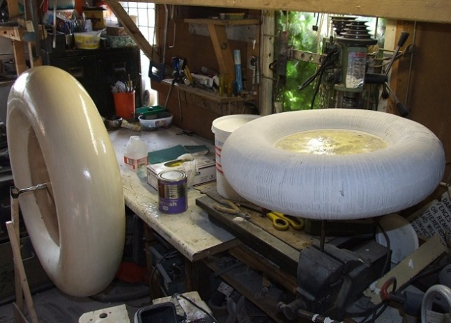
As well as the new 8.5 x 34.5 inch, I am also constructing a smaller 4 x 18 which may be needed underneath the main toroid, to help shield the top of the secondary.
Here is the last, and most tedious stage of the whole project.
The three inch wide foil I used can be difficult to apply without any creases, as you're applying a wide two-dimensional flat foil onto a curved three-dimensional surface. One inch wide would have been ideal, but would have taken for ever, so with hindsight I think two inch is a good size on larger toroids, and one inch on smaller ones.
Fortunately it will smooth out quite well with something like the back of a spoon being rubbed over it. You must though use a piece of paper between the foil surface and the spoon otherwise the foil will tear. I find the discarded backing paper of the foil itself is excellent for this.
You can still achieve good acceptable results with smoothing away creases, even if it looks awful when you first apply it, so don't get too disheartened with the initial creases.
You will not however get a nice smooth surface like that of a professional spun aluminium toroid, but the finished product will be smooth enough to avoid having lots of little break-outs that normally occur with just bare heating duct.