Rebuild of my 8 Inch Tesla Coil (1)
So with a view to fitting an even larger and heavier toroid one day, and maybe even a bigger secondary, I decided to completely rebuild the base of the coil.
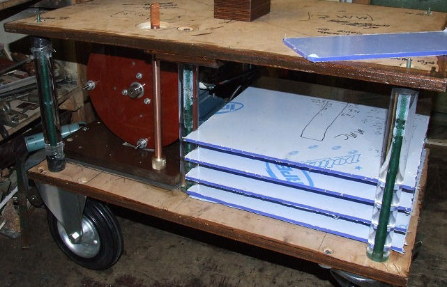
The new base was to be much heavier to provide both stability and robustness, so 0.7 inch [18mm] exterior plywood was used. This then had extra bracing glued, and screwed across the middle lengthwise. I then decided to cover the top exposed surface of the board with 3mm black Acrylic sheet, while the primary was to be protected by a blue 5mm circular top sheet, that sits about an inch above the primary coil itself.
The MMC consists of 4 trays of blue 5mm Acrylic sheet, that can be pulled in and out for easy access should a capacitor need replacing at any time.
(Update 2014: Later another tray was added for 125nF total)
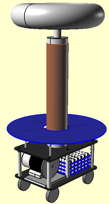
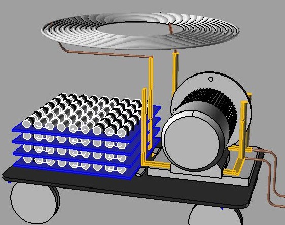
A CAD representation of the finished coil: ("The Phoenix")
The top and bottom boards are separated by six, 11 inch lengths of 1.4 inch diameter, clear Acrylic rod. This has been drilled down the centre to take some threaded rod. These Acrylic rods serve the purpose of clamping the top and bottom boards rigidly together.
In an effort to be able to experiment with the coupling more, I proposed to make it easy to adjust, by simply pulling out the yellow pins (Shown below) and placing them in a higher or lower hole. This will allow the whole primary assembly, whose four legs project through holes in the top level's board, to be easily raised or lowered.
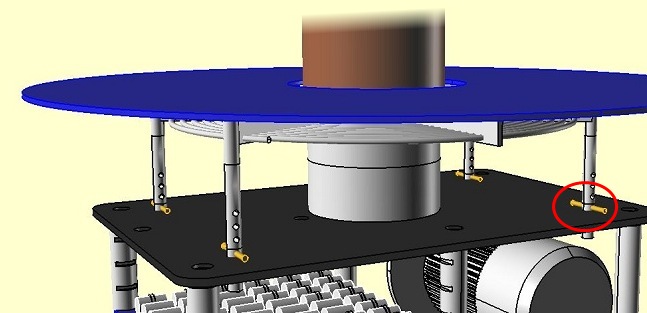
Proposed Coupling Adjustment
(Circled in red)
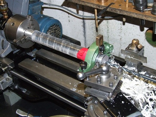
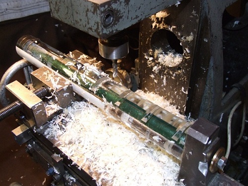
Drilling the Acrylic legs for the threaded rod
The drilling however has caused the central hole to have a rather crazed appearance, due to it being magnified when viewed, rather like the mercury in a thermometer is.
Sliding MMC Trays
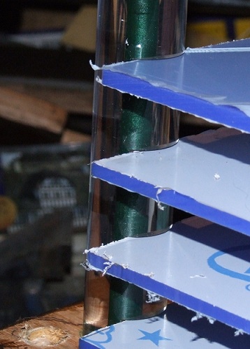
Milling the 0.25 inch slots for the MMC trays
New Secondary Mounting
The previous secondary mounting was very unstable as it was originally designed for a 4.7 inch coil with an 18 inch toroid.
The much larger toroid I now use (34" x 8" or a borrowed 50" x 11") combined with the 8 inch secondary, means that trying to use it outside with a light breeze, could be very hazardous unless the mounting was made sturdy.
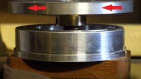
The method you can see in the following pictures ensures not only a good earth connection, but rigidity. The mating surface of the two flat rings is around 4" diameter, so when screwed tight against one another there is no chance of the secondary rocking or swaying in a breeze.
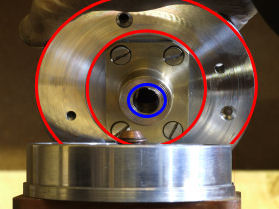
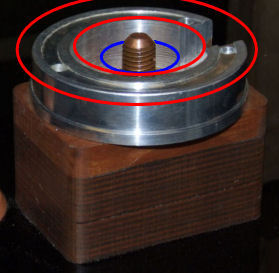
The aluminium and brass mounting on the base of the secondary has a central threaded boss (circled in blue) that screws down onto the copper threaded rod (shown below, also circled blue).
This allows the outer surface of the secondary's mounting plate (circled red) to engage against a matching Aluminium surface on the lower part. As the secondary is rotated it then screws itself down and locks tightly, so no movement is possible.
Although most likely not needed, the lower mating surface has a slot cut into it in case it acted as shorted turn.
The base of the secondary is just a normal flange that doubles up as both a mounting point and also the secondary's lower connection to earth.
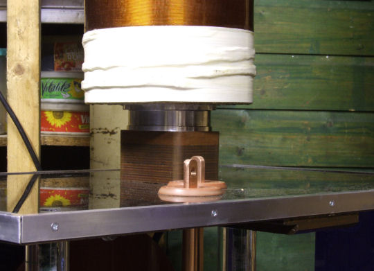
Screwing the secondary down......
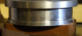
...... until it's fully home and tight.
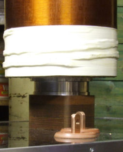
The secondary is now in place and locked tight against the bottom mating surface.
This is necessary if you wish to use a big toroid, and also the rigidity allows the coil to be moved in situ without having to take the toroid off.
The vertical copper bar you can see, goes up to the primary, although a far larger diameter than what is needed, it was spare, so put to good use. My aim is to have copper busbars (0.625" x 0.25") for the feeds where possible, with as few loose leads as possible in the tank circuit.
This will hopefully mean the primary frequency stays reasonably fixed, rather than varying due to different lead positioning whenever I reassemble the coil. This variation in frequency has in the past been as much as half a primary turn.
This can sometimes mean the simple action of tuning by altering the primary tap lead and then feeding it a different route to a new position elsewhere on the primary, can sometimes make little difference to the resulting frequency, a point often overlooked.
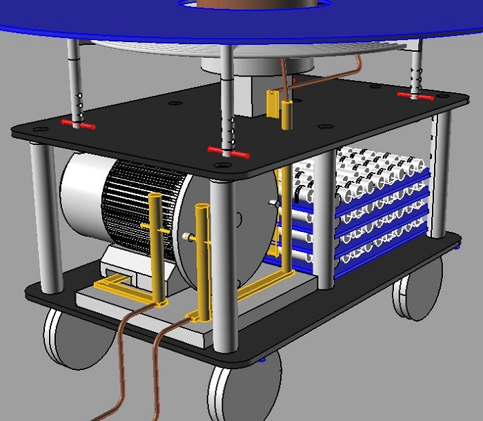
The eventual idea is to have copper bars (shown as yellow above) forming most of the tank circuit.
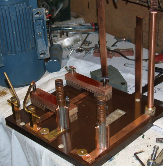
The basic layout of the SRSG board (Tufnol) takes shape.
Here you can see where the copper busbar has to pass underneath the SRSG motor mounting.
The oblong depression (right side) milled into the base board is to provide clearance for the bottom of the 12" rotor.
(I wish to keep the coil as low as possible to avoid ceiling strikes - things are very tight!)
Wiring Circuit
The individual trays of capacitors for the MMC will each terminate onto the two vertical busbars.One of these bars for space reasons, has had to be routed underneath the main SRSG motor as seen above.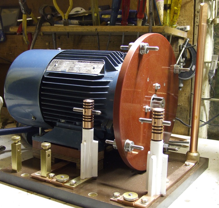
The Finished SRSG
2Hp 3000rpm
The two upright brass pillars to the bottom left, will hold the horned safety gap. The HT input connections are the two round brass terminals (middle & bottom right). The tall copper rod (rear right) will go through into the top level and will have one end of the primary tap connected to it. While the copper bar running under the motor will go to the MMC.
The above photo should be renamed 'almost finished' because I later modified things again.