Tesla Coil Pictures 3
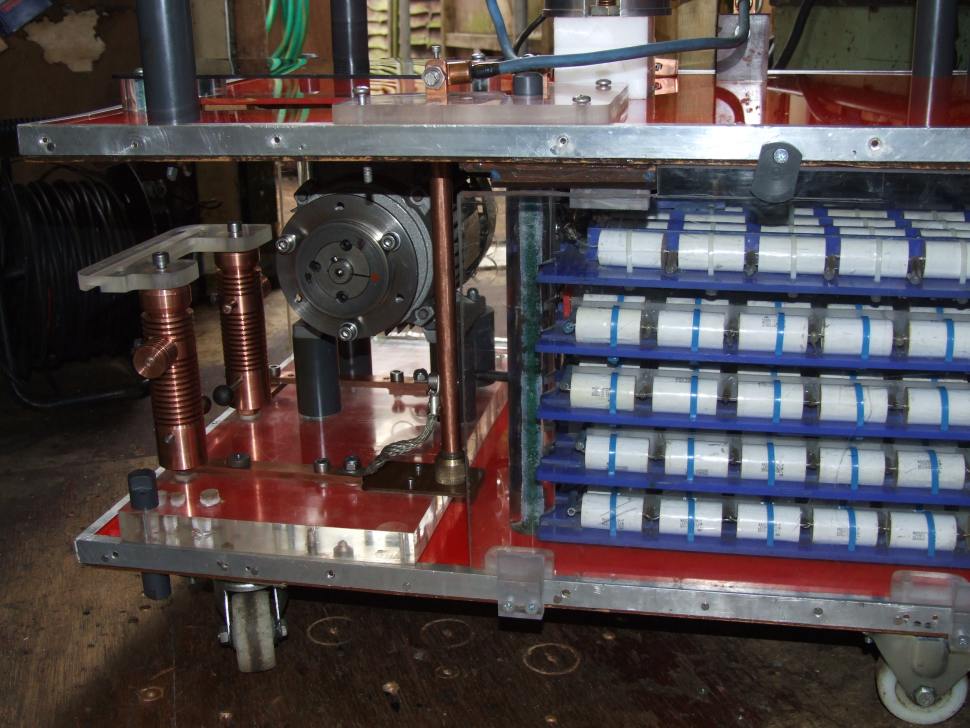
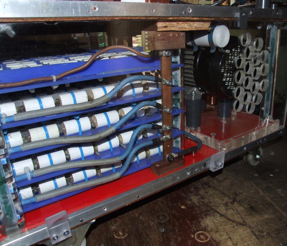
These five trays of capacitors are each 25nF, making a total of 125nF. Each tray has two connections to a solid copper bus-bar, and here we can see one of them. The other one is located in the middle of the coil and serves the primary connection.
To remove a tray the two connections are easily undone and the sliding tray of capacitors pulled out, making access relatively easy despite the lack of space.