SRSG Construction
![]()
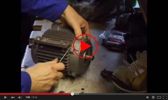
Building an SRSG Part 1
This consists of two videos.
This first one gives an explanation of the method, and follows on to correct motor selection, followed by the actual modification (in this case by milling).
![]()
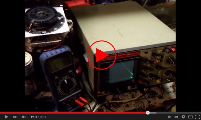
Building an SRSG Part 2
This second video shows the necessary testing afterwards, followed by the building of a phase controller, (including capacitor size selection) based on John Fraeu's design.
The use of a fairly easy to construct phase controller is the only way you can be certain you have the correct phase position., so it's important not to ignore this last part of the construction.
First success was on a 1440 rpm 4 Pole
(This became salient pole at 1500 rpm)
The width of cut is explained in the video.
Second motor was a 2880 rpm 2 Pole
(Became salient pole at 3000 rpm)
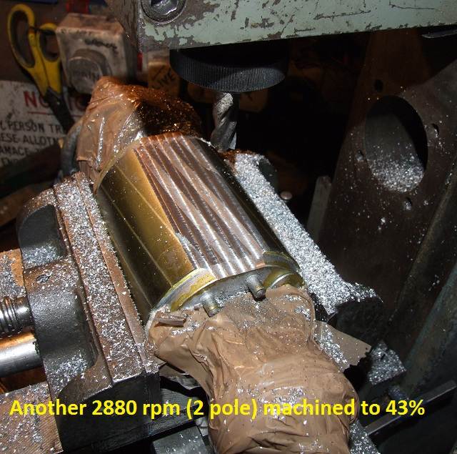
Then along came another 2880 rpm (1.5HP)
This was done for someone else using a 43% width.
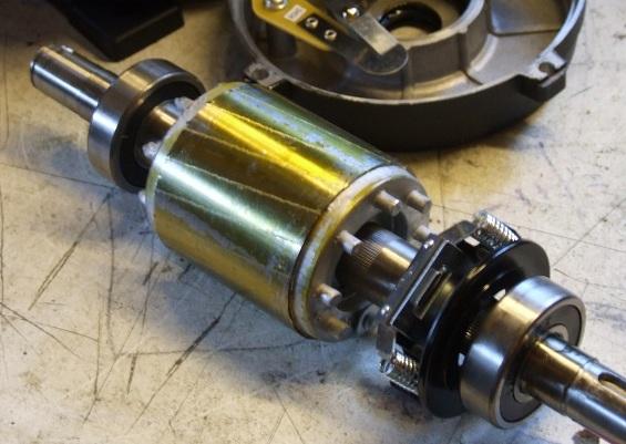
Here we can see the rotor as removed from the motor, and prior to having any work done on it. It's often easier to just leave the centrifugal switch and bearings in place, as either can be rather difficult to remove.
The centrifugal switch in particular being prone to cracking as it's often only made from a hard plastic.
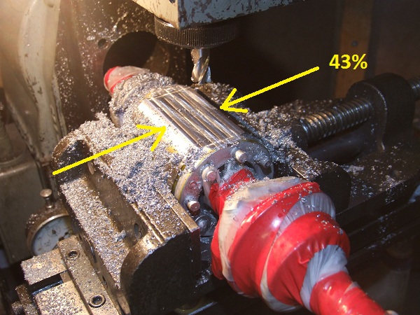
After conversion
Note the thorough covering of the centrifugal switch and bearings - metal particles in any of those parts would be the death of them.
Another motor (the 4th) I undertook
The fifth motor I converted was filmed and used in my two SRSG videos at the top of the page.
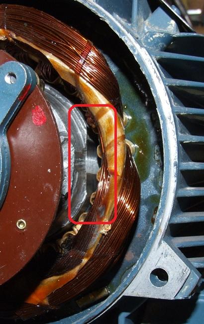
The Machined Flat Is Ringed In Red.
This will be explained fully below,
(motor is a two pole 2880 rpm, with a 40% cut).
------------- 18th Dec 2010 -------------
'Penfold Motor Conversion'
Another possible way of achieving a Synchronous motor, which I personally have not tried, has recently come to light. It discovered by British coiler, Clive Penfold, and utilises an old washing machine motor, which only needs a small amount of work with a soldering iron.
The full details can be found in these newsgroup postings:
TCML Post
Electrokinetica.org post
4HV.org post
I am uncertain though if a phase controller works with this method.
A SRSG for a Tesla Coil
Do These Modifications At Your Own Risk(To aid clarity and avoid confusion,'Asynchronous' will be written in Blue, while 'Synchronous' will be in Green)
An ordinary unmodified induction motor is an Asynchronous motor which means it will always rotate slightly slower (2% - 6%) than the rotating magnetic field created in the stator, this is called slippage.
To make a Synchronous Rotary Spark Gap though you will need either a Synchronous motor, or an ordinary AC induction motor that has been converted to (in effect) what is salient pole operation. The word salient in this context meaning dominant.
The rotor of a truly Synchronous motor, will always rotate at the same speed as the rotating magnetic field created by its surrounding stator. The speed of this rotating field always having a direct relationship with the frequency of the AC supply and the number of poles the motor has.
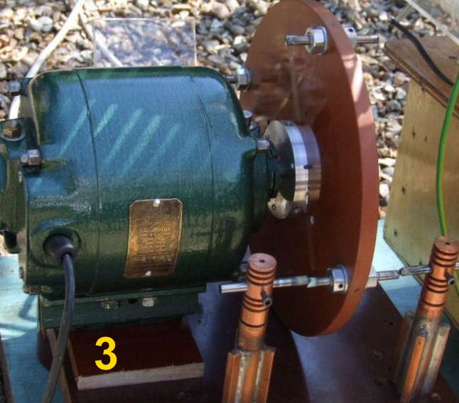
The Theory
Let us suppose we have a Synchronous (or in effect a salient pole) motor running while you are monitoring the sine wave of its AC supply. Then when the supply voltage is at the peak of its sine wave, let's imagine you were able to magically freeze both the motor's shaft and the display of the AC sine wave.
If you then made a mark on the shaft in relation to the casing somewhere, you would find that every time the marks subsequently aligned, the AC wave will always be at the same point in its cycle. The position of the rotor is fixed to the sine wave therefore.
Do the same trick with an Asynchronous motor and you will find the marks and the position of the AC cycle, will not align as they will be constantly changing. The position of the rotor in this example, is not fixed to the sine wave.
Back to the Synchronous motor again, in reality, dependant on the number of poles the motor has (2 or 4 are the only types we use), you will have either 2 or 4 positions around the rotational path of the shaft where the shaft's mark aligns with the mark on the casing.
As mentioned a normal induction motor's rotor revolves slightly slower than the magnetic field influencing it, this is built into the motor (increases torque) and is called 'slippage', making the motor Asynchronous, but by machining some flats on the rotor you concentrate the magnetic flux and cause it to lock to the rotating field - so it's now Synchronous. On a two pole motor this would mean locking to one of two positions, or one of four on a four pole motor.
As this speed is now directly linked to the AC supply sine wave, which in turn charges the capacitor, you can now arrange things so the gap fires, at a time when the capacitor will always be fully charged.
With Asynchronous motors the mains cycle could be at any point on the sine wave curve when the electrodes align. The capacitor therefore may, or may not be fully charged, resulting in a weak, or even a missed firing.
Asynchronous motors can still be used - as long as the breaks per second (bps) of the spark gap is higher than around 400, as over voltage is not such an issue then.
An excellent in-depth analysis of rotary spark gaps can be found here at the very knowledgable site of Richie Burnett.
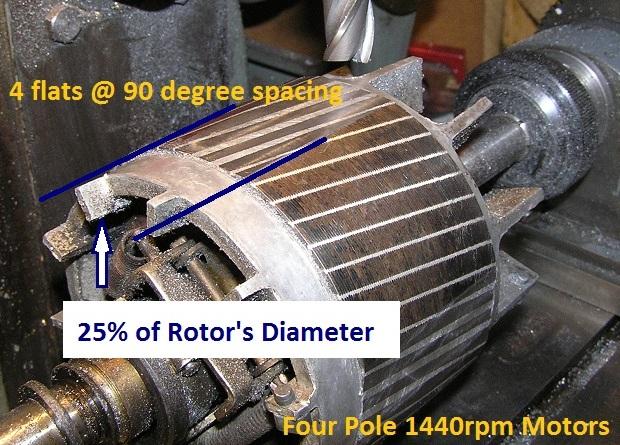
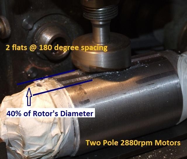
If the motor is a 1440 rpm (1800 on 60Hz) it has four field windings and will need four flats milled onto the rotor, each at 90 degrees to one another. If the speed is 2880 rpm (3600 on 60Hz), it only has two field windings and consequently only needs two flats at 180 degrees to each other.
After modification the speed, if all is working correctly, will have increased to either 1500 or 3000 rpm (1800 / 3600rpm 60 Hz), and some may run a bit hotter or with less power. The last 2Hp motor I did though, is the only one that has ever ran hot, with a 3 minute run leaving the shaft a bit too hot to touch!
So the amount removed when forming the flat is reasonably important. Too little and the motor will not be Synchronous and its speed will constantly surge or 'hunt'. Too much and it will lose too much power and overheat.
The loss of power would vary, although it hasn't happened to mine so far, others have not been so lucky though. The secret of success is to use an oversized motor (power wise) at the very outset.
Vibration can also be a problem if the machining is not done accurately.
With four pole 1440 rpm motors I measure the overall diameter of the armature and remove one quarter or 25% of this distance as a flat.
For the two pole 2880 rpm motors, the width of the flat I remove is around 40% - 43% of the rotor's overall diameter (see video 1).
I did try 30% on the second motor I machined (2880 rpm) and while this worked with just the bare 10 inch disk, when I added all the Tungsten electrodes the added weight then caused it to unlock and become Asynchronous again.
By removing another 10% to make it 40% overall, the motor worked perfectly in Synchronous mode.
All of the modifications I have done have gone well with no obvious power loss. The 1500rpm motor was a 0.5 Hp so any loss of power with that one would have been noticeable, whereas the others have been 3000 rpm units with larger powers, so had plenty of leeway anyway.
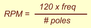
Pic 1:
Example of a badly designed SRSG
The 1500 rpm motor had an 8 inch rotor with the electrodes on a 7 inch PCD. The 8 electrodes giving a break rate of 200bps at 1500 rpm. As the tungsten electrodes are 0.25 inch diameter on a PCD of 7", this combined with the 1500rpm speed meant the mechanical dwell time of the rotor was very poor.
All the RSG's I have built since use a two pole 3000rpm motor. This also has the advantage of only having to machine two 'flats' at 180 degrees to one another. As ensuring the four 'flats' are all at 90 degree to each other is a lot harder, and prone to cause vibration if any error is present.
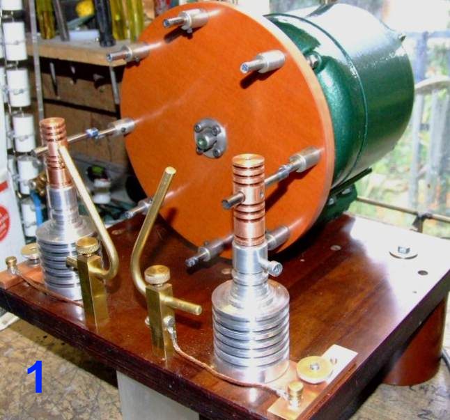
Pic 2:
As can be seen despite the staggered electrodes I still suffered badly from power arching, caused I think by the closeness of the 8 electrodes on the disc, (I used a conducting ring on the rear of the rotor). I felt the main reason was that the motor was only 1500 rpm, so for that reason I built number 3, with a slightly bigger rotor.
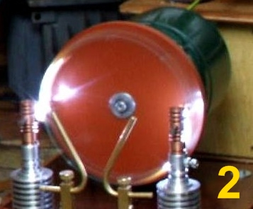
Pic 3:
This is my second attempt now using a 10 inch disc. This was still 200bps but without the conducting ring on the rear of the disc now. This meant I now needed two separate pairs of stationary electrodes, with one pair at 9 o'clock and the other pair at the 4:30 position on a clock face. When this is combined with four rotating electrodes on a 1500rpm motor it gives 200bps (honestly).
Unfortunately the 0.25 inch diameter electrodes combined with the 1500 rpm, still gave a poor dwell time, with power arcing at much over 3KW. For that reason I then used the 10 inch disc on a 2Hp 3000 rpm motor I had modified. The 3000rpm meant I only now needed four revolving electrodes and just one stationary pair mounted conventionally either side.
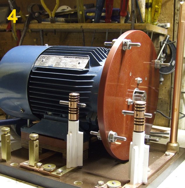
2HP 3000rpm with 10 Inch Rotor
Pic 4:
This is the third attempt, with 10 inch rotor from the second build now on a 3000rpm 2 HP motor. It has two stationary electrodes and four revolving. All electrodes are 0.25 inch Tungsten.
I used copper bar as much as possible, rather than wire, with the large vertical copper bar at the rear going up to feed the primary.
Unless you use a manufactured pulse cap though, the thin leads of each MMC capacitor will always be the resistance bottleneck, but thick copper bar elsewhere, helps keep the remaining resistance low.
New Motor
Unfortunately this motor got hit by a streamer, so it had to be replaced, followed shortly with the Tufnol base flashing over. This lead to a complete rebuild of the SRSG on Page 2, followed by another in 2015.
See both links below.
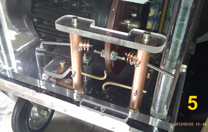
Pic 5:
After the 2013 rebuild
The 2013 SRSG Rebuild
Latest update:
The 2015 SRSG Rebuild