Pole Distribution Transformer
Pic 1:
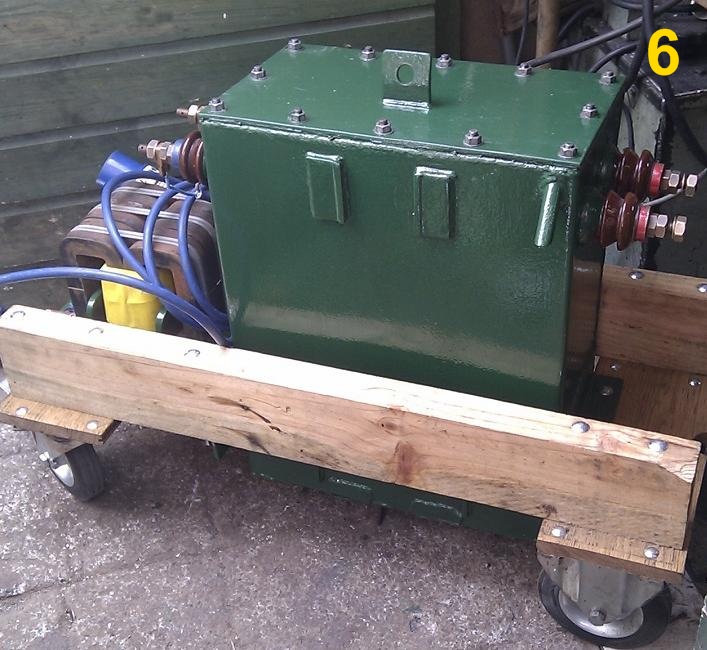
The PDT as it was when I acquired it.
I had just finished making my own HV transformer when I saw this Pole Distribution Transformer (PDT) for sale. These are ideal for a big tesla coil, so unable to resist it, and with no thought given as to how heavy these things are, I decided to buy it. After completing a 435 mile round trip to collect it, with thankfully someone lifting it in for me, I decided to test it by running a Jacob's ladder. Using the 250 volt : 11550v taps I fed in 263 volts which gave 12kV out.
As these units are built to a high specification for continuous running in all temperatures, I decided to ballast the transformer for 500 m/a at 12kV giving 6kVA (original specification was 5kVA continuous) The secondary current is therefore slightly overloaded from the manufacturers continuous run specification of 454 m/a.
Pic 2:
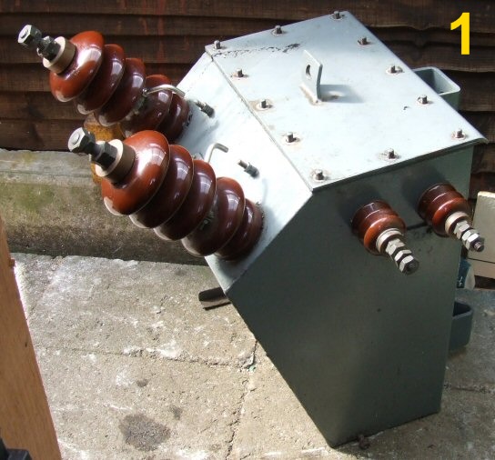
The total height is 16 inches. Weight of cores is 90 Pounds
The two secondaries are each wound over their respective primary winding. I am unable to ascertain the number of turns or the gauges of the wires that have been used.
Pic 3:
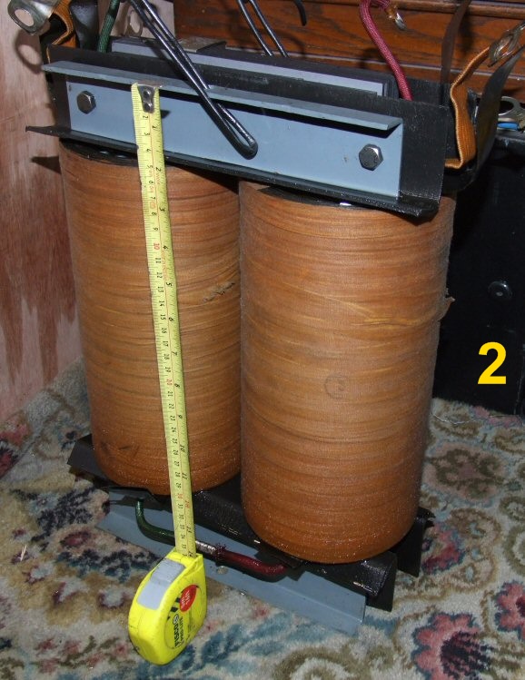
The trolley mounting now makes it easier for my long suffering family to move around, as I'm disabled. The front of the case that originally bulged outwards with the two big input insulators, had a triangular section from each side area cut away, the remaining front flap was then bent upwards, and all was welded shut.
Originally the two pairs of small insulators on each side were the outlets to the load, and by various combinations of these four inputs a voltage range of 10.45Kv to 11.55Kv input could be used.
As I was using the transformer in reverse I only used the 11.55K / 250 volt combination, leaving two terminals unused. I then altered the wiring inside to use this spare pair as the new output, now that the big front insulators were removed.
When fed from a variac that gives 110% of input voltage, this gives 12K+ output.
The amount of oil was also reduced but this will not present any problems for short term Tesla use.
I know the welding is poor, but as I only had a cheap Chinese arc welder at the time that gave a very questionable 90 amps, (and also cut out every 5 minutes from overheating) it was far from an easy task.
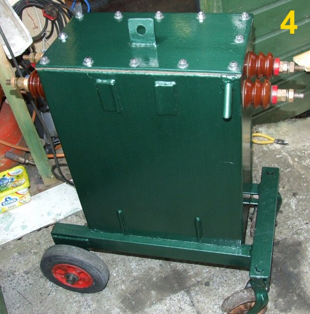
Pic 4:
Low voltage (250v) on the left side, HV output on the right (marked red).
The remains of the two cradles that allowed the transformer to be pole mounted are still visible.
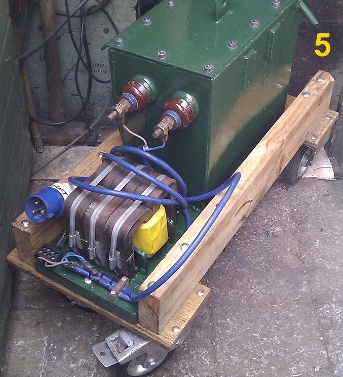
Pic 5 & 6:
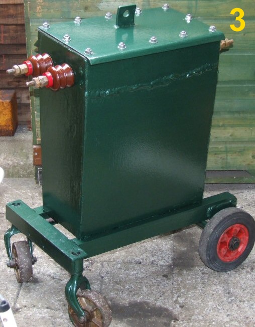
Later on I made a more robust trolley, that also housed the ballast as well. The total weight of the whole affair is now 340 Pounds / 154 Kg
This new trolley now has a much lower centre of gravity making it far more stable when transporting.