DIY Transformer (Page 1)
Remember: Transformers with high current can be Lethal.
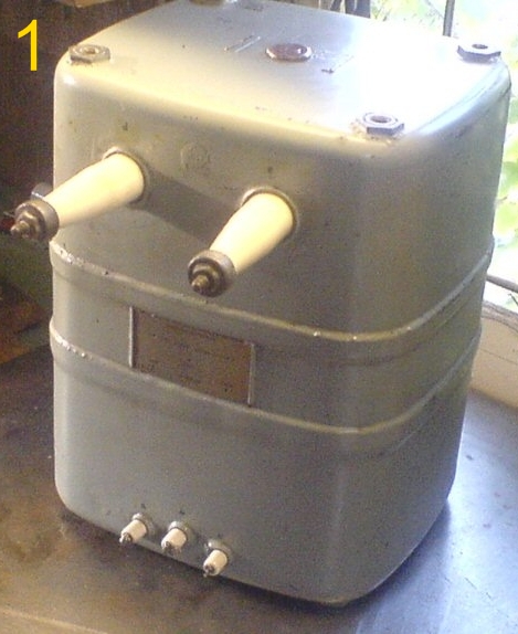
1: The donor transformer: 8.25KV 0.25 Amps
The original transformer had a burnt-out secondary winding when I was kindly given it for free. My aim with this project was to provide a robust tesla coil power source, allowing me to move away from the fragile Neon Sign Transformers.
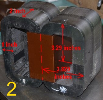
2: The original bare cores once removed
You may wish to skip this first section if your not interested in the theory.
Originally the secondary winding was wound conventionally around the primary coil on the middle leg. The all important cross-sectional area of this centre leg, where all the cores meet, was 8 square inches. I say important, because larger cores are better at dissipating heat among other things.
The amount of flux created depends on things like: core size and material, input voltage and the primary inductance, etc.
As you ultimately want a high turns ratio, you will want the minimum number of primary turns, that will not saturate the core.
Transformer design is actually quite complex, and the usual simplified textbook explanation can lead you to wrongly think it's easy to design one. Aware of this from my own teenage college years, I took the easy path and used the existing primary specifications. If you also choose this path, don't stray too far from the original specifications, as manufacturers tend to design the primary to be as close to saturation as possible from the outset, without it actually occurring.
If though you need a completely new primary, there are several standard formulas for calculating both the core size needed, and the number of turns, but these all depend on you knowing the magnetic permeability of the core material, and also assume that the coefficient of coupling is close to one (1).
An approximation can be found by taking the square root of the expected power and multiply that figure by 0.14. Meaning my intended 5800 watt DIY transformer, should have had a core size of sq root(5800) * 0.14 = 10.66 sq inches, in reality it had 8 sq inches.
A transformer for electronics or particularly audio use, has to be built to a high standard. But a homemade transformers for tesla use, only really needs to fulfill two requirements: a high output voltage, and the ability to supply as much current as possible.
So assuming you are using a proper laminated core, and not an old pipe packed with welding rods, an acceptable formula that I found that will give a starting point, is to measure the cross sectional core size in sq inches. This measurement we will then call 'A', the input voltage will be 'E', and 'K' will equal 6.5 for a 60Hz system or 7.507 for 50HZ.
Number of primary turns = (K * E) / A.
Using this figure on my core I got a figure of 222 turns needed to create sufficient flux.
The number of secondary turns is worked out like this:
222 turns / 240 volts = 0.925 volts per turn on the primary. Assuming a coefficient of '1', a secondary of 10,000 turns will develop 10,000 * 0.925 volts = 9,250 volts.
So firstly wind the 222 primary turns and connect it to the mains to check that your unloaded primary current, the so called energising current, is not too high. Allow up to ~5% to 10% of the max expected short-circuited primary current, for this energising current. Remember though that the bigger the core, the higher the energising current will be.
Next, once your happy with the number of primary turns, it's a good idea to just wind a temporary secondary coil of [say] 50 turns using the full core. Then measure the induced voltage in that and divide by 50. In a perfect world this would equal the 0.925 volts that the earlier example's calculation gave. But if instead you get 0.7 volts and you still want a 9,250 volt output, you will need to adjust the number of secondary turns, worked out by: 9,250 / 0.7 = 13,214 turns.
Although the formula actually gave 222 primary turns for my own core, in reality I found the original only had 130 turns. This may be due partly to the permeability of the core material, on which I have no data, but mainly because it used a bifilar winding. So on my primary of 130 bifilar turns, (130*2) 260 / 240v input means each primary turn will carry 1.083v.
I had decided to use two secondaries wound on each outside leg, (for reasons explained below), therefore each secondary of 5432 turns will develop 1.083 * 5432 = 5884 volts and their combined voltage is 11,769v. Due to losses and less than perfect coupling I actually have ended up with 10.87K, one side delivering 5.51K, the other 5.36K.
As mentioned the coefficient of coupling is generally assumed to be close to '1', but this almost certainly will not be attainable with home wound transformers, unless using a transformer winding machine. This is mainly because the layers will never lay perfectly flat on top of one another, which incidentally, can also make the windings much larger than you had originally planned for, so care is needed here.
As an example:
If you used 20 thou wire, in a winding that is 10 inches wide you should in theory get 500 turns per layer (10/ 0.02) In practice you may end up with a 20 thou wire followed by a 2 or 3 thou gap before the adjacent winding. So each winding in effect takes up on average 22.5 thou. 10/ 0.0225 = 444 windings instead of 500.
So if you had originally planned on 30 layers of 500 equaling 15,000 turns in total, you will now need 15,000 / 444 = 34 layers.
Each layer also needs insulation paper, and this you will find is the main cause of a bulky winding.
The very first layer of 20 thou conductors with 5 thou of insulation will most likely become 26 or even 27 thou as the paper will not lay dead flat.
But the next layer, in addition to the problem just mentioned, may also not sit level on their underlying layer, so subsequent layers may be up to 30 thou, instead of 25. Also remember that any bump or unevenness on an inner layer gets far worse by the time it has got to the outside.
As mentioned already I simply rewound the primary with new wire using the same specifications as the original. You may even be able to use the existing primary wire without unwinding it.
The secondary wire that I used was 0.4mm / AWG #26 / SWG #27). After a lot of time looking at different tables for wire amperage I used a figure of ~500 circular mills per Amp (cir mil/amp) but only because the windings are under oil.(use 1000 to 750 cir mil/amp in air. A 'cir mil' = diameter of wire in thou squared)
The calculation is: 0.4mm = 15.748 thou, squared this equals 248 cir mil, 248/500 = 0.5 (0.495) Amps. The ballast actually gives 537 m/a with the primary drawing 21 amps.
The bifilar primary winding is AWG #14 / SWG #16 wire. The current capability using 500 cir mil/amp is 8.25 Amps. The bifilar winding though means it will carry 16.5 amps.
As the depth of the winding is not too deep the oil should be able to circulate easily, so for this reason I run at a max of 21 amps. The oil and the actual winding only getting warm to physical touch.
The weight of the whole assembly in the box with oil is 31 kg or 68 pounds.
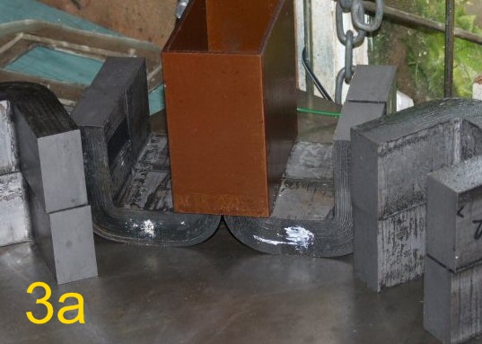
3a: The cores are in matched pairs.
It is most important that you keep the pairs (top and bottom) together, as they will have the best fit on their mating surfaces, important if you want a consistent value from the inductor.
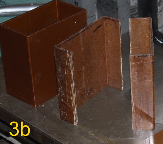
3b: Making the two secondary bobbins
I was also given a large inductor that used the same cores and centre leg bobbin as the radar transformer. As I was going to wind the new transformer with two secondaries, one on each outside leg, I now needed two extra bobbins. I decided therefore to modify the bobbin that came from the inductor, by cutting it in half and making two, as can be seen above on the right.
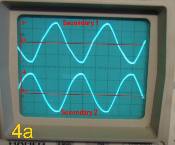
My winding arrangement meant that each coil should output just under 5.9 kv, but most importantly both windings were wound out of phase to each other. This means that when one coil has its outer end at 5.9Kv positive in respect to its inner end at zero volts, the second coil will have its outer end at 5.9Kv negative to its inner end. As the two inner ends are always at zero volts they can be linked together. This means a connection to the two outer ends will result in having a combined voltage of 11.8kv at 50hz.
4a / 4b: The phases relationship of the two secondaries
Another reason for this arrangement is less voltage stress on the windings. NSTs also use this system to keep their construction costs down, but they also ground the centre tap to the core, which I didn't.
To wind this out of phase arrangement, imagine you are looking at the coils from the top or plan view. Starting the windings at the top, I wound one winding clockwise and the other anti-clockwise, with the primary sitting in the middle. This arrangement, shown in picture 4b, allows you to have the inner low voltage ends of both windings at the same physical end, meaning you only need a short link between them to join the zero ends together.
Some transformers will automatically limit their current when the secondary is short-circuit. This feature occurs if there is a flux path created by the primary that doesn't interact with the secondary. This then causes a current limiting effect to occur that would be the same as placing an inductor in series with the secondary. Transformers that have this feature built in include NSTs, welders, MOTs etc, and it is achieved by having so called shunts (metal inserts), bridging the gaps between the core's legs. This characteristic can also occur if there is an excessive leakage flux, which is the case with my own transformer.
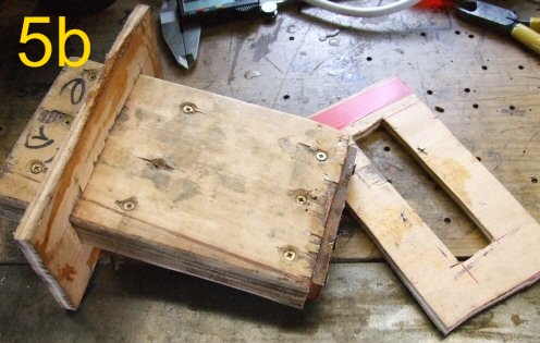
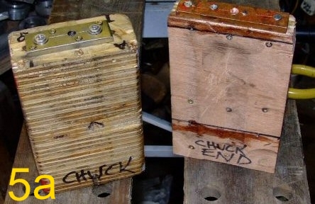 5a 5b: Both wooden mandrels
These mandrels are the same size as the legs of the core. In 5a the left hand one is for the larger middle leg, while the thinner right hand one is used for the two outside legs. The wooden mandrels are gripped in the chuck of the lathe, and a plywood side piece is slipped on (see 5b). Next the bobbin is slid on, followed by another plywood side piece. The latter being held in place by a couple of small tacks.
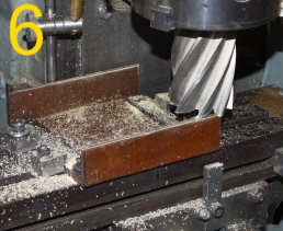 6: The edges are milled flat
I glued a flat rectangular piece of phenolic sheet to the freshly milled edges of the old bobbin to make the fourth missing side.
This is used between each layer and serves two purposes.
a: It acts as insulation, as the adjacent layer above and below can be several hundred volts higher or lower respectively. The wider each layer is, the more the voltage difference is. With for example a 10,000v NST with two 50 layer coils of 5,000 volts each, then each layer handles 100 volts. The voltage difference for a point at the end of a coil to the end of the layer immediately above or below could be 200 volts though!
Also remember that peak voltages are 1.414 times the RMS value. This is why you have the paper half an inch each end wider than the actual winding of the wire (see #13 below).
b: It allows you to get a much neater winding, which is very important if you want to pack as many turns as possible in.
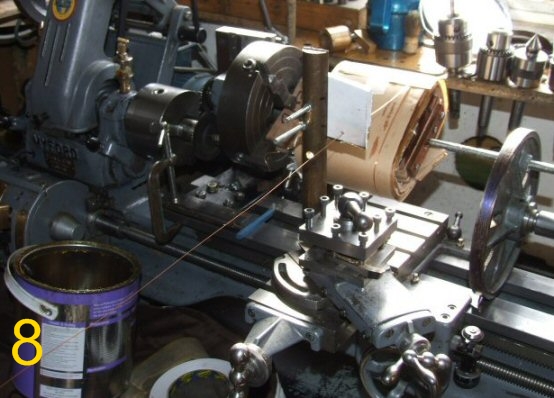
8: The setup on my lathe
This rather cumbersome setup (8) was needed as the centre height of the lathe is not enough to allow for a fully wound coil. The chuck of the lathe is driving another chuck which is raised above the lathe bed, allowing more room for the coil to swing around in.
I have used the same method to wind several Secondary coils as well.
In those cases I removed the tail stock of the lathe and fixed it to the bench further away, this then allows any length of secondary to be wound.
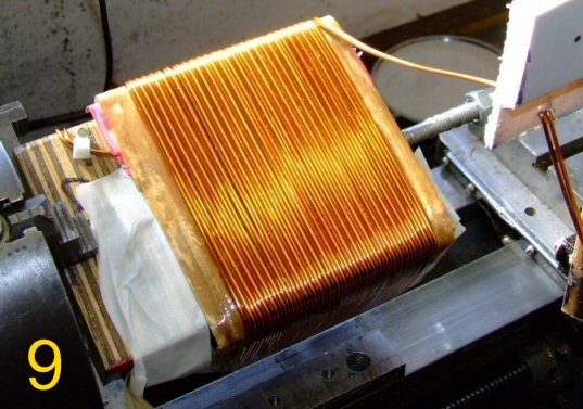
9: The Primary bifilar winding. AWG #14
Because the thick wire needed some two-handed work I left the side pieces off when winding this for better access, and just positioned the paper by eye.
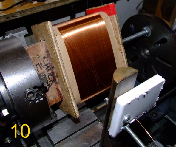
10: One of the Secondary AWG #26 windings
In each case the lathe's screw feed was engaged and a suitable gear was employed that would, on each turn of the mandrel, only move the saddle the same distance as the wire's diameter.
The lathe was run at around 30rpm to 60 rpm. I am fortunate to have a variable frequency drive with a foot operated switch, therefore making the whole procedure far easier to handle. I also did a couple of test runs with some old magnet wire to fine tune my procedure first though.