Phase Controller
This is a very handy little circuit from a respected and authoritative American coiler.
(He got the idea in Dec 2000, with his original TCML posting being Here).
*** Update 9th April 2011 ***
The trouble I encountered with the original circuit above is that the high start current of the motor goes through the Variac winding. In my case this amounts to 16.5 amps for my 2 Hp motor, albeit for a short 0.5 second or so.
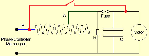
I therefore decided to modify the circuit as shown below. The switch circuit (shown in red) simply bypasses the variac winding and the fuse during starting. Then once the motor is turning at speed you simply open the switch to put the variac into circuit.
You may, or may not find this modification necessary with your own controller, as it all depends on the motor size that you use, as to the amount of starting current.
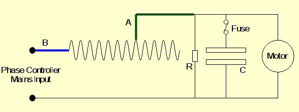
The circuit uses the combined inductance of a Variac and the motor, along with a large uF value capacitor, to alter the phase angle. As the motor's own inductance value affects things, the only way to get the right value is by trial and error. I found a 124 uF of capacitance with my 2 Hp motor (3000rpm) and a 34uF with the 0.5 Hp motor (1500rpm) was needed.
*** Update 16th Oct 2010 ***
John Freau, said in a recent TCML posting that he thinks that a 120v motor (60Hz USA & others) may require up to 4 times as much capacitance as a 240V 50Hz motor would. So it seems there are many factors at play when deciding on the capacitor size required, the most important one being the distribution system in use where you live (240v 50Hz or 120v 60Hz).The best way to ascertain the capacitance value is to start with around 20 to 30uF and the Variac set to zero, so it is not introducing any inductance into the circuit at this stage. You then need to slowly increase the Variac and at the same time monitor the voltage across the motor looking for a rise.
You only really need to have up to a maximum of a 10 volt rise at some point after which the voltage should then drop down again as you further increase the Variac. You need to go slowly though as it is all to easy to get a potentially damaging 30 volt rise or greater if your capacitance value is too large to start with. My 0.5Hp motor actually uses a 15v rise without suffering however.
If you find you get no rise at all you will need more capacitance. Too much voltage rise means the capacitance value is too large. With both my motors I found steps of around 5 uF in value can make quite a difference - but other motors may differ.
You often find that even with a capacitance value which is correct (i.e. giving a modest 5 or 6 volt rise) that as you approach maximum inductance on the Variac's scale the motor will loose sync'. But as long as you have around 60 to 70 degrees of electrical phase adjustment for a 100bps or 40 to 50 degrees for a 200bps you will probably find that is sufficient to operate with initially.
After initial setting up you can then move the rotor's position on the shaft so it is very near its optimum position prior to starting. Trying to start the motor with some phase adjustment already "dialled-in" can make it draw a high starting current, and also cause a slow run-up to normal speed.
I then found that when you switch the power off to the SRSG it exhibits a severe self braking effect, where you can actually hear the motor noise being rapidly de-accelerated. This is caused by the phasing circuit and can, I would imagine, damage the motor over time. I found a multiple switch that disconnects both the mains feed to the controller and the feed to the motor at the same time solves this.
However you must have some bleed resistors across the capacitors though if you use this method. Otherwise the exposed metal pins of the plug will have the capacitor's stored voltage across them. On one occasion I pulled my phase controller's mains plug out and laid it onto the metal work-top and there was an almighty "crack" as 124 uF charged to 250v discharged itself into the bench!
Also don't run the circuit with the motor disconnected either, unless you want some smoke from your Variac. That is the reason for the fuse in series with the capacitor.
To determine how much phase movement you actually have you really need to have an oscilloscope. You can then set the rotor to trigger a photoelectric cell which is connected to one channel of the oscilloscope, while the other channel has a low voltage AC mains source as a comparison. You must however make sure that you position the photo electric cell exactly at the point that the electrodes would normally come into alignment.
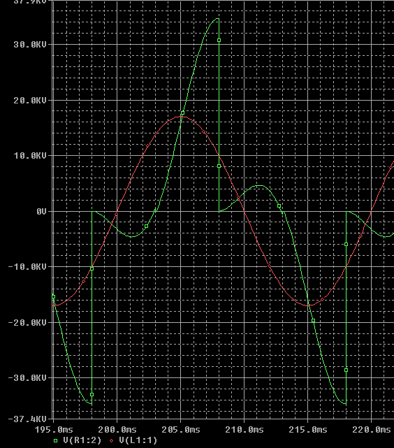
Failure to get the phase setting correct will result in one of the firing voltage graph's peak being much lower and the next peak much higher. This will manifest itself by the coil sounding wrong and having reduced output. It usually also causes the firing voltage to rise dangerously high at times stressing the MMC's voltage rating, and causing the safety gap to fire.
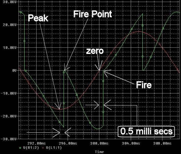
Taken to extremes it would mean a 200bps tesla coil could in theory become a 100bps coil as you can see in the simulation below. Here I have retarded the firing point to 3 millisecs resulting in a very high peak at the point 3 millisecs after the mains sine wave has peaked, and virtually no voltage at the firing point that occurs 3 millisecs after the mains has crossed zero. This is something that I will try - one day!
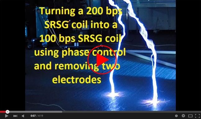
Update: 12th June 2010.Out of curiosity I decided to see if this idea would really work. The YouTube Video I made unfortunately has been deleted by mistake, but it showed that you actually can alter the phase to get different bps rates. However as the coil was on very low power at the time, the actual performance, when running at full power, has yet to be assessed.Recently I tried the same thing again, but this time I removed one set of electrodes before adjusting the phase to an extreme setting. The video shows the results at 100 bps working, both with and without a breakpoint.
Click on Picture >>
![]()
100bps Experiment
The best phase setting seems to be at around 0.7ms for 200bps and around 2.0ms for 100bps, at much over 2.5ms the coil sounded very rough, so I did not pursue that anymore.
These timing figures mentioned are only based on a very approximate scale marked on the control variac, which I had previously calibrated using an oscilloscope and photo electric cell.
You cannot of course allow for the fact that in reality, the voltage on the stationary electrode will have the tendency to jump to the approaching electrode, long before the terminals have actually aligned themselves.
This is even more evident if you start the coil at half input voltage on the variac and tune the phase control to the right setting. If you then increase to full voltage, then what was the ideal phase position at half voltage will most likely not be suited for full voltage.
On my first SRSG, a 1500 rpm 200 bps example, this was very evident, and needed carefully monitoring. My later 3000rpm 200 bps SRSG I now use is no where near as critical in this area for some reason.
Variac
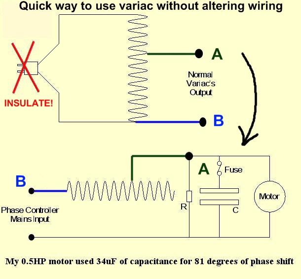
If your variac is wired up for everyday use (plug on main input going to top and bottom of inductor, 'live' or 'hot' to the top and neutral to the bottom) it is still possible to use it quite easily without having to open it up and re-wire it. Just use the normal output of the variac as shown in the circuit below.
If you do this be sure to insulate the pins on the now unused inlet plug of the Variac, as they will become live during operation.

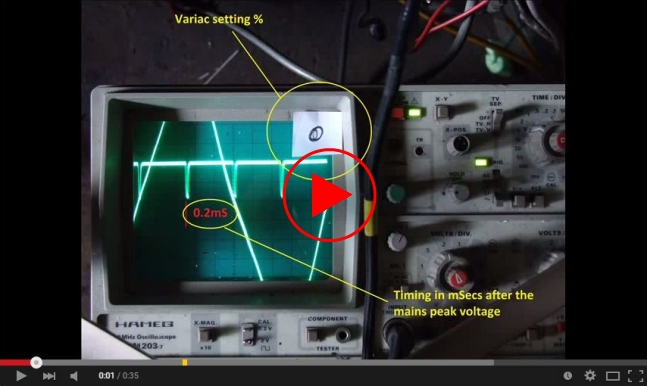
My video below shows the four firing points (the four downward, two division deep spikes) move in relation to the fixed mains frequency sine wave, as the variac setting is altered in steps of 10%. The result is that the timing ends up shifted almost back to where it stated from.
The figures in red near the scope's centre, are the timing in mSecs of the firing point after the mains peak. The variac setting is shown on the stickers on the scope's screen at top right.
![]()
Despite personally liking the simplicity of a blown static gap, to get the best result from a larger tesla coil though, I have found that an SRSG is the way to go. They not only handle large amounts of power well, they also give a consistent and predictable bang, unlike the somewhat random nature of a static gap. This can be very useful if you want to analyse the things like the coil's ring-down with a scope, for example.
The 200bps SRSG has a unique sound that is unlike a static or ARSG. This is particularly handy for tuning the coil with the phase controller. At the correct setting the coil's sound smooths out, and takes on a very identifiable steady tone when phased correctly.