
Undergoing Maintance as Images are missing. 8/Jun/2010
Mounting the Clock
First consideration is to find a suitable vibration free solid wall; essential if any decent timekeeping is to be achieved by a Synchronome. A solid external wall rather an internal non load bearing wall is also preferable. As a lot of new houses now use hollow plaster board for internal walls you may be limited in your choice though. So choose an area where the temperature is constant, away from radiators for example, but do try to avoid any place where the sun is capable of shining into, or onto, the clock case.
When hanging the clock and choosing your fixings, remember the main weight of the clock is taken by the top central bracket, the other fixings are to stop any lateral movement. It is best to use a plumb line that is suspended midway between the two brackets that support the pendulum at the top of the movement. This should align with a point midway in the bottom of the case, and should also align with the central web of the casting at the top. Particular care should be taken in getting the case aligned vertically front and back as well, as it may be the wall you are placing it on is not vertical.
I have my clock mounted away from the wall slightly with the gap filled with rolled up bubble wrap. I cut it into strips and rolled these into sausage shapes and then packed them behind the back of the case in the 1/2 inch gap (down to 1/4 inch where the battens cross the case back) that I had created. This helps to quieten the clock a bit when it operates, as the back can act like a soundboard. They are not particularly noisy, but at 3am they can be (how can I tactfully words this......) 'annoying' if your not an 'enthusiast'. Also keeping the voltage down helps, but only to a level where it is still capable to reset quickly and cleanly each time. Excessive voltage only succeeds in making more of a 'clunk'. Another side effect of the bubble wrap, although a smaller one, is that the back of the case is insulated from any cold walls.
The method of mounting I came up with was chosen to ensure I could get a solid 3 point fixing and, if needed for decorating purposes, I can easily remove the clock and replace it in exactly the same orientation, without using a plumb and spirit level each time.
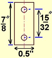
I made up two small 1/8 inch thick brass pads each about 3/4 inch long. They had a central blind hole 1/4 inch or so diameter and two small holes either side that passed all the way through to take some panel pins. These were then secured with the pins to each bottom corner on the back of the clock. The blind hole in each then aligns with a suitably pointed bolt head or screw shank screwed into the wall. By screwing the bolts in or out during installation, it will then allow perfect vertical plumb to be obtained. A single screw then inserted through the case (via an existing central hole at the bottom) into the plugged wall, then effectively clamps the case hard against the wall by way of the 2 pointed heads of the wall bolts locating in their respective holes in the brass pads.
Getting the two wall holes to align with the pads was the tricky bit. I made up two dummy rods that fitted snugly into the holes of the brass pads. These also had a pointed end where they pressed against the wall. I then hung the clock on its top bolt and screwed the top bolt home so that there was no in or out movement when you pushed and pulled the clock case against the wall. Don't over tighten the top bolt or screw, otherwise it will start to tilt the bottom part of the case outwards and away from the wall.
Once I had got the central line plumb (a spirit level on the case's side will do initially before using a plumb line inside) I then pressed the clock case hard into the wall so the pointed ends of the dummy rods marked the plaster. Once the wall is then tapped I chose some suitable bolts or screws that would locate in the brass pad's central holes, but without having any free play, and these were screwed into the wall.
Once the clock was hanging on the top mounting I gave it a gentle push in and it located itself on the two bottom screws. There is now no sideways movement even if I push on the side of the case. Lastly a bottom central screw through the case and into the wall, then effectively clamps the case against the wall.
__________________________________________________________
The following adjustment instructions are based on a reissue by Synchronome in 1972 of those that they gave to their customers, and also those from Mr A Mitchell of the Antiquarian Society in 1978.
The Suspension Spring
It is usually good practice to fit a new suspension spring when you acquire one of these clocks, if however the spring shows any form of damage it is vital to do so. Suspension springs can be bought from horological suppliers like Meadows & Passmore or else have a word with your local clock maker or repairer (not so easy to find in the High Street nowadays)
Punching a hole through some spring steel with a flat-ended punch can make the necessary holes. You must make some form of die up to hold the spring though, as it is critical that the holes are carefully aligned and spaced. Car feeler gauges can be a good substitute for the correct spring steel; though they might not quiet have the width needed.
Why all the fuss over the spring? Well the bob weights 16 pounds, and it is suspended from a strip of metal 5 thousands of an inch thick that flexes 86400 times a day, or 2.5 million times a month. As the average age of a clock is likely to be 50 years, work it out yourself!
The spring should be carefully placed in the top chop and the screw tightened. It is imperative the spring is 'square' in the chop. Laying the chop on its side while tightening on a flat surface, after you have removed the trunnion, enables you too see if you have an equal gap between the side of the spring and the surface. The other end of the spring is next inserted in the bottom chop that is still attached to the rod, making sure that the two spring tightening screws in the top and bottom chops are on the same side as one another.
The bottom chop's screw should be tightened just enough so that the spring can still moved without any slop, if you hold the rod in your hand and push against the spring with your thumb. As a test after tightening I held my rod, with no bob on, upright by the trunnion, and pushed against the bottom of the rod. It should come back to vertical or almost vertical but only with some resistance. When in service with the bob's weight added that last little bit of resistance will be overcome. The reason for this arrangement is that when the pendulum is hanging in the case it needs to be able to have movement in the fore and aft direction. When all the adjustments are finished the trunnion will be clamped to the top pendulum bracket, so it won't have the ability to swing at that point if any slight accidental knocking of the bob occurred. If the spring was tight in both chops, then almost certainly the spring would bend or kink when knocked.
The gathering arm will be fitting into the slotted screw at the rear of the pallet once everything is complete, but it is best to first acquaint yourself with how it pushes in and tilts over to one side, before fitting the pendulum in the clock. To avoid any damage to the gathering arm remove it again before proceeding with the installation of the completed pendulum into the case. The depth, or angle, that this arm is allowed to drop down when it engages a tooth, is a critical measurement and for that reason the actual screw that the slot is cut in, is just a friction fit in the pallet. The method of adjustment being that you just need to push lightly down on the arm, once everything is in the case, to get some extra depth. Too much depth is awkward to get rid of without removing the rod and bob again so gentle pressure (on the steel rod and not on the actual jewel) is required, along with constant checking. However the screw can sometimes be adjusted back if you do have too much depth, by removing the gathering arm with the pendulum in situ, and then using a cranked 'home-made' tool and mirror to see the screw head around the back. I got my smallest Allen key and ground the tiny hexagon end away to a very thin flat that just fitted into the screw's slot.
Obviously it pays to start off with not enough depth to the arm. This is best ensured before hanging the pendulum by gently turning the screw a 'tad' anti-clockwise with the back of the rod in front of you out of the clock.
When you assemble the bob note that there is normally a small nick in the rod about a foot or so from the bottom, and this indicates where the top of the bob should be in order to start off with an approximation of correct rate.
________________________________________________________
Setting the Pendulum Up
When you hang the pendulum in the case, ensure that the trunnion sits cleanly between the two top brackets, with the reduced diameters sitting well seated on their respective bracket tops. Once the pendulum is hanging in the case you can then, working blind, locate the gathering arm in its hole, and once in its slot let it fall over towards the 'count' wheel. You will most likely have to swing the pendulum over by hand to the far right of the case, this allows the gathering arm to then fall against the wheel's teeth. Leave the depth adjustment of this till later on. You will now need to align the fore and aft position of the pendulum so that the gathering jewel engages with the 'count' wheel teeth in the middle of the jewel's face. This is achieved by carefully sliding the trunnion on the top bracket, either inwards or outwards from the back of the case.
It is also most important to get the pendulum swinging 'square' in the horizontal plane, by that I mean its path should be parallel to the back of the case. After I had got the position of the pendulum where I thought it would be all 'square' I measured the gap between one end of the trunnion and its adjacent threaded stud on the pendulum bracket. If everything is square the gap should be the same both sides. By sliding different drill bits in I was able to measure the distance. I then turned up two little round rods of the size needed and put them in temporarily between each end of the trunnion and its adjacent stud. Then I pulled and pushed the pendulum assembly to make sure the trunnion was hard up against the temporary rods, and they in turn were hard against the studs. You can be sure everything is really parallel that way. Remove the temporary rods and tighten the two top trunnion clamps up with their wing nuts.
The pallet should have a clearance of 10 thou where it swings under the roller 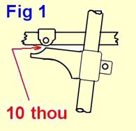 (Fig 1), but a clearance less will do as long as you don't go too small; I think mine is about 4 thou. Some people think a smaller drop gives fewer shudders to the pendulum when the impulse occurs, so take your choice. To adjust this gap you cautiously loosen its clamp, and using a piece of wood being knocked by a screwdriver, raise or lower the pallet. Undo the screw too much and the clamp will become sloppy and drop down the rod. You must also make sure the pallet is exactly in line with the swing horizontally, otherwise all the work you done on the top trunnion to get it parallel was wasted!
It may not be enough to assume that the pallet is already aligned correctly in this horizontal plane just because it was previously running. If it is misaligned it will cause the pendulum to have a slight wobble when the roller drops onto it. The end of the pallet has, besides the obvious circular impulse ramp, a slight radius to it in the fore & aft direction to take care of any error like this, but it is best to get it as good as possible yourself by eye.
You will now need to loosen the small grub screw that clamps the top chop to the trunnion, this will allow you to slide, with care, the pendulum either left or right. Get the rod central to start with, and then release the gravity arm by turning the wheel around until the roller very gently lowers onto the pallet. Make sure the pendulum is not pushed off centre at all while doing this, and it remains dead central. The central pivot of the roller should now align with the corner of the pallet (Fig 2).
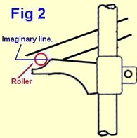
There is some discussion with owners on this point though, as some feel it should instead just 'barely' drop onto the top surface of the pallet just above the corner. The Synchronome instructions quote alignment with the corner though.
If the roller's pivot appears to be above an imaginary line drawn to the corner you will need to slide the pendulum assembly on the trunnion to the right. (I actually lever the chops over with a screwdriver - as they won't slide easily because of the bob's weight). Once aligned correctly tighten the grub screw up that locks the top chop to the trunnion. You will now need to check the pallet's 10 thou clearance again to make sure the setting has not altered.
________________________________________________________
Adjusting the Buffers
Now you need to adjust the reset buffers and the contact gap.You will need the gravity arm to be reset and held by the clamp as per normal for these adjustments.
First you need a 10 thou (0.26mm) gap between the pole face "A" (Fig 3) and the armature or reset arm, when the magnet is energized. This is essential other wise the arm will 'stick' due to residual magnetism when the magnets are switched off. Hold the armature against the left-hand buffer "1" (Fig 3) and adjust the buffer till you have the required 10 thou gap at point "A".
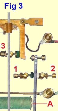
Next, keeping the armature against the same buffer still, adjust the contacts screw to give a gap of 70 thou (1.8mm) between the two contacts. Next release the armature and rest it against the right hand buffer "2" (Fig 3). You now need to adjust this buffer until you have a 212 thou (5.4 mm) at the contacts.
Next there is an adjustable spring at the bottom of the armature and this needs to be adjusted so that there is just sufficient tension to ensure the armature returns back to the buffer when the magnets release. When the magnets are not operated this spring may appear to have little tension; that is quiet normal though.
There is just one final buffer "3" (Fig 3) to adjust, though early models before the mid 1920's did not have this fitted. This buffer decides how far the gravity arm travels up when re-setting takes place, and should be set so that the gravity arm is barely touching it when the arm is normal. If the catch does not mange to latch properly you may need to adjust this, but too much gap will cause noise and vibration.
The gathering arm depth must now be adjusted. This is done, as I have already mentioned, by gentle pressure pushing down on the wire rod. This is best done by pressing in the middle of the rod, as then you get the benefit of some leverage, but not too much spring from the rod itself. Don't use the small brocot jewel (the red ruby) to press on. These are only stuck into the wire loop by shellac.
Make sure the wooden beat scale that sits into the bottom of the case is centrally located, such that the '0' is aligned with the end of the rating thread.
A gentle push so that the pendulum swings to at least 2.5 on the scale either way is needed before the gathering arm will gather a tooth in correctly.
Once the clock is running the amplitude should increase and settle to around 3.5-0-3.5 or 4.0-0- 4.0 after a couple of hours. If the bob was raised initially to align with the notch in the rod you will have an approximate position to get the right time.
________________________________________________________
Battery Voltage.
Synchronome recommended 4 volts for their master clock with its single built-in slave dial, although I have had them running on 3 volts and latching perfectly each time. Synchronome advised that any further slave dials that were added need the addition of one volt for every three ohms of extra resistance. I later added two slave dials to mine at home and then ran it on 6 volts.
Maplin incidentally do a nice double 6 volt lantern battery (Jan 2007 code: ZB66W) that is ideal for this use. By breaking open the cell you have access to two 6 volts cells in parallel. Each 6 volt cell is made up from four 1.5 volt 'flag' cells. This allows you any combination, 3v, 4.5v, or 6v. You can also add a suitable low value resistance if you so wish and keep the battery as a complete 6 volt cell. Synchronome recommend a current of 0.33 amps when the clocks operate, though again you may get away with a bit less. Some clocks came with a variable resistance built into the case much like a Gents did, allowing you to get the correct current from a large range of voltages quiet easily.
Too much voltage will cause not only excessive noise, but extra vibration, so is best avoided. Too little voltage however will cause the mechanism to latch either slowly or incompletely, the later manifesting itself as multiple latches, (an onamatapaeic staccato 'ber-derr'..'ber-derr'..'ber-derr' instead of a single defined 'berr-derroomph') Also the slave will very briefly clunk, but the hands, although they will judder, will not move onto the next dial division. A tell tale sign of this is to find you are suddenly loosing time in multiples of 30 seconds.
Even if the mechanism latches perfectly and the clock steps on each time, check the action of the magnets still. The very
instant the contacts touch, the magnets should attract the armature. If it hesitates at all that is also a sign of a low voltage, and means the roller is running down the pallet past the point it is meant to.
________________________________________________________
Rating
Rating the clock is the next and longest stage as it will take weeks, if your lucky, or most likely months to get it 'just right'.
See this page.
Original Synchronome Literature and Instructions